



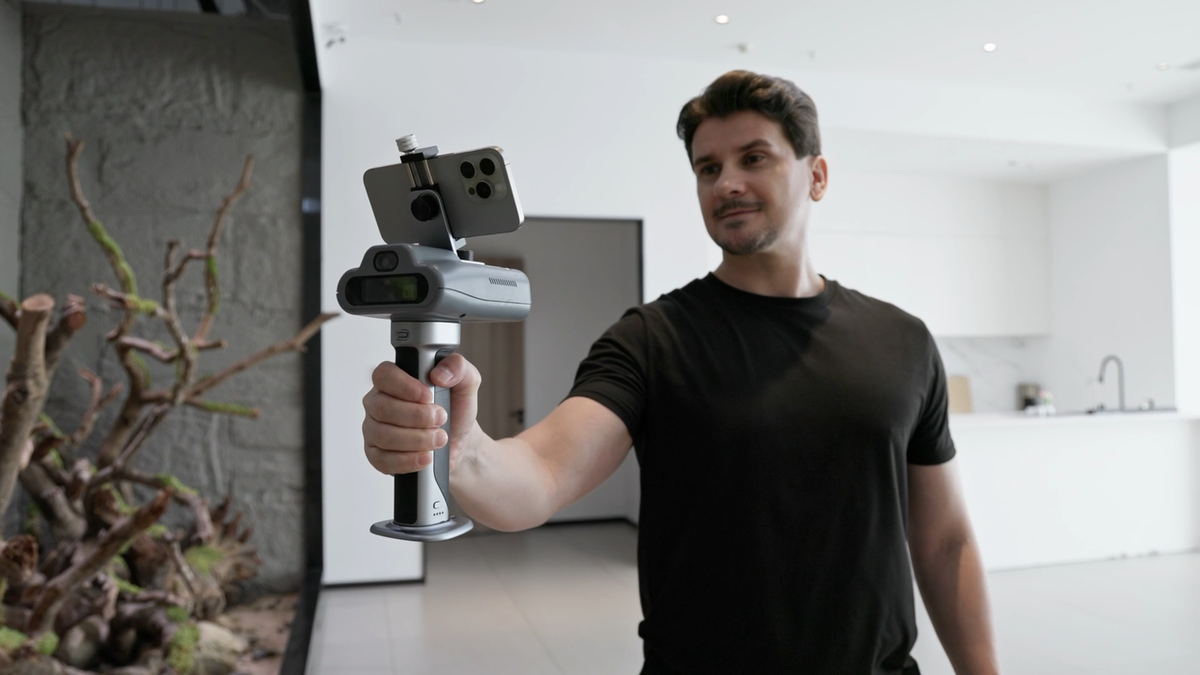
A site visit should leave the design team with more than a page of dimensions and a camera roll full of disconnected details.
A scan-to-floor-plan workflow captures the room as connected spatial data. The designer can check coverage before leaving, develop the floor plan against the captured conditions and export editable CAD geometry for the work that follows.
Why site measurements break during drafting
Traditional site measurement collects information piece by piece. One dimension describes a wall. A photograph records the window. A sketch shows the door swing. A note on another page explains the ceiling change.
That method can work, but every fragment must be interpreted and reconstructed later. The designer may only discover a missing opening or uncertain dimension after the property is no longer accessible. A second visit may be the only reliable answer.
Room scanning changes the starting point. Instead of recording selected measurements alone, the operator captures visible room geometry as a connected spatial record. The floor plan can then be created, checked and developed against that record rather than reconstructed from memory.
What “editable DXF” means in this workflow
An editable DXF provides selectable CAD geometry rather than a flattened floor-plan image. It gives the design team a base for further work in compatible CAD software, but it is not automatically a finished construction drawing.
After import, check the units, scale, wall geometry, openings and project-critical dimensions. The file may still need office layers, annotations, drawing conventions and professional review before it is used for permits, fabrication or construction.
Creative Portal supports 2D and 3D outputs for compatible projects, including DXF, GLB, SVG, PNG, JPG and PDF. Model Web can generate DXF and PDF floor plans from compatible V4e Go projects. In both workflows, the exported DXF can be opened and edited in compatible CAD software.
Choose the right floor-plan route
C1 and V4e Go both support room-to-DXF work. Choose the route according to the capture experience and deliverables the project requires.
| Product and workflow | Floor-plan process | Handoff |
|---|---|---|
| C1 → Creative app → Creative Portal | Review the generated floor-plan draft, check highlighted gaps and add laser measurements, then refine walls and openings | Export an editable DXF and floor-plan report |
| V4e Go → Creative app → Creative Portal | Use the captured 3D data as the spatial reference while creating or refining the floor plan | Export an editable DXF and other project outputs |
| V4e Go → FJD Trion Scan → Model Web | Generate DXF and PDF floor plans automatically from compatible scan data | Open the DXF in CAD for further design development |
C1 is the focused choice when an indoor floor plan and onsite dimension checks are the main requirements:
| C1 capability | Published specification or workflow benefit |
|---|---|
| Rapid indoor capture | Up to 200 m² (2,153 ft²) in about three minutes under stated conditions |
| LiDAR capture | 230,400 points per second across a 140° × 56° depth field of view |
| Post-processed relative accuracy | Up to 1 cm (0.4 in) under stated conditions |
| Built-in laser | ±3 mm (±0.12 in) for checking key dimensions onsite |
| Drafting efficiency | Up to 80% less manual drafting in FJD Trion internal tests on selected interior design projects |
Actual capture time, accuracy and drafting savings vary with the space, surfaces, operator and workflow.
From room scan to editable DXF
1. Define the area and deliverable
Confirm what the project includes before starting the scan.
Does the designer need one room, an entire floor or a set of connected spaces? Is the next deliverable an existing floor plan, a CAD base for renovation, a measured property record or a presentation drawing?
List the dimensions that control the next stage. Cabinet runs, appliance openings, stair details, door clearances and custom fabrication may require separate verification to the project’s specified tolerance.
2. Prepare the space
The room does not need to be empty, but its defining geometry must be visible from the capture route.
- Open internal doors where access is permitted
- Move small objects away from important corners
- Identify furniture that conceals critical wall sections
- Note mirrors, glazing and reflective finishes
- Check how narrow passages connect with adjoining rooms
- Plan how to cover stairs, voids and ceiling changes
Take supporting photographs where finishes, fixtures or partially obscured areas may need a visual record later.
3. Select the capture workflow
Use C1 or V4e Go with the Creative app when the main deliverable is an indoor floor plan developed in Creative Portal. Plan a continuous route through doors and around corners so adjoining spaces remain connected.
Use V4e Go with FJD Trion Scan when the project also needs Model Web point-cloud processing, automatic floor-plan generation or broader 3D deliverables.
The scanner and software route should be chosen before capture because the required output determines what must be observed onsite.
4. Capture connected room geometry
Move steadily through the space and maintain coverage as you pass through doors and around corners. Include:
- Wall junctions and room corners
- Doors, windows and other openings
- Floor edges and level changes
- Ceiling conditions that affect the design
- Fixed elements that affect the layout
- Connections between adjoining rooms
C1 records 230,400 points per second across a 0.1–6 m (0.3–19.7 ft) range. Its published post-processed point-cloud specification is up to 1 cm (0.4 in) relative accuracy under stated conditions. Good results still depend on coverage, surfaces, capture path and operator technique.
5. Check the capture onsite
Do not wait until the room is no longer accessible to discover a gap.
With C1 in the Creative app, review the generated floor-plan draft, check highlighted gaps and add built-in laser measurements to key areas. With V4e Go, check scan coverage in the Creative app before upload. When using FJD Trion Scan, inspect the live point cloud for missing rooms, incomplete wall sections and openings that need more coverage.
Before leaving, ask:
- Is every required room present and connected?
- Are important doors and windows visible?
- Did the capture include ceiling conditions that affect the design?
- Are irregular or partially obscured walls represented clearly enough to review?
- Have fabrication-critical dimensions been verified to the required tolerance?
6. Build the floor plan
For a Creative workflow project captured with C1 or V4e Go, upload the capture to Creative Portal. Use the captured 3D data as the reference while creating or refining walls, doors and windows. Review how the plan represents genuine angles, irregular boundaries and the connections between rooms.
For a V4e Go project using the Model Web workflow, upload the scan for browser-based point-cloud processing and automatic DXF and PDF floor-plan generation.
Automation provides a faster starting point. It does not remove the need to compare the result with captured conditions.
7. Review the geometry
Check the plan room by room before export:
- Confirm wall positions and room boundaries
- Preserve genuine angled or irregular walls
- Check doors, windows and other openings
- Review how adjoining spaces connect
- Compare uncertain areas with the 3D record and site photographs
- Mark conditions that were inaccessible or could not be verified
The aim is not to make the drawing look cleaner by forcing every corner into a right angle. It is to create a usable plan that reflects the captured space.
8. Export and verify the DXF
Export the DXF after reviewing the main geometry. Use a descriptive project name and confirm the intended unit system.
Open the file in the receiving CAD application and perform a handoff check:
- Confirm drawing units and overall scale
- Compare at least two known distances with verified site measurements
- Check wall lengths, openings and room connections
- Confirm that the required entities can be selected and edited
- Review angled walls rather than forcing them into right angles
- Establish orientation and a clear reference point
- Apply the office’s layers, linetypes and drawing standards
- Retain the PDF, mesh or point cloud when it helps explain the geometry
“Editable DXF” describes the geometry. It does not mean that the drawing already follows every firm’s CAD template or is ready for construction.
What changes in site-to-CAD work
The room remains available after the visit
The captured 3D record gives the team a spatial reference to revisit when questions appear later. Photographs and notes remain useful, but they no longer carry the entire burden of explaining the site.
Coverage can be checked onsite
The operator can review the captured space before access to the property ends. C1 users can also inspect the generated floor-plan draft and highlighted gaps in the Creative app.
Key checks stay connected to the project
C1’s built-in laser, rated to ±3 mm (±0.12 in), allows targeted measurements to be added during the same capture workflow.
Drafting begins with captured geometry
The CAD user receives editable geometry rather than rebuilding the room from a sketch. The first task becomes checking and developing the base instead of recreating it from isolated measurements.
Common scan-to-DXF mistakes
Beginning without defining the output
A scan intended for a basic floor plan may not capture everything required for elevations, reflected ceiling plans, millwork details or a BIM model. Define the deliverable before the visit.
Moving too quickly through transitions
Maintain coverage when connecting rooms. Slow down where the geometry changes, the view is obstructed or the route passes through a narrow opening.
Accepting the first floor plan
Review walls, boundaries, doors and windows against the captured 3D record. Automatic generation shortens the path to a draft; it does not remove the need to check it.
Assuming the DXF is construction-ready
The file may still need verified dimensions, layers, annotations, drawing conventions and professional review. Permit, fabrication and construction uses can impose additional requirements.
Discarding the 3D reference
Keep the scan and supporting record when the client’s data policy allows. A plan cannot always explain an unusual ceiling, partially obscured corner or irregular connection as clearly as the captured space.
When V4e Go extends beyond the floor plan
V4e Go supports both the Creative Portal and Model Web routes. Use the Creative workflow when the main result is an indoor floor plan. Use FJD Trion Scan and Model Web when the project also needs a broader point cloud and 3D deliverables.
In Model Web, compatible V4e Go scan data can support measurement, DXF and PDF floor plans, OBJ models, 3DGS models, virtual room walkthroughs and AI-generated interior renderings. The exported DXF can be opened and edited in AutoCAD or another compatible CAD application.
V4e Go also supports indoor and outdoor capture. An optional compatible GNSS receiver can add positioning when an outdoor project requires georeferenced context. GNSS is not required for a standard non-georeferenced indoor room scan.
Choose C1 for a focused room-to-DXF workflow with a generated floor-plan draft and built-in laser checks. Choose V4e Go when the same scanner also needs to support broader point-cloud, 3D or indoor-and-outdoor work.
Frequently asked questions
Can C1 create an editable DXF floor plan?
Yes. Capture the indoor space with C1 and the Creative app, review the generated floor-plan draft, refine the compatible project in Creative Portal and export an editable DXF.
Can V4e Go create an editable DXF floor plan?
Yes. Use V4e Go with the Creative app and Creative Portal to create or refine a floor plan and export a DXF. Alternatively, use FJD Trion Scan and Model Web to generate a DXF floor plan automatically. The exported geometry can then be edited in compatible CAD software.
Can I open the DXF in AutoCAD?
Yes. AutoCAD supports DXF. After opening the file, verify units, scale, orientation and entity behaviour, then save it in the working format required by the project.
Is the exported DXF construction-ready?
Not by default. Treat it as an editable base. Verify project-critical dimensions and add the layers, annotations, drawing conventions and professional review required for the intended use.
Should I choose C1 or V4e Go?
Choose C1 when indoor floor plans, a generated onsite draft and built-in laser checks are the main priorities. Choose V4e Go when you also need Model Web processing, broader 3D outputs, AI interior rendering or connected indoor-and-outdoor capture.
Start CAD work with a clearer record
The value of scan-to-DXF is not the export button. It is the continuity between the physical room, the captured spatial record, the floor plan and the editable geometry handed to the design team.
Capture deliberately. Check coverage and key dimensions before leaving. Review the plan against the 3D record. Verify the DXF before developing the design.
Products for this workflow


FJD Trion C1
Explore More

FJD Trion V4e Go
Explore More
FJD Trion Creative Portal
Explore More
How to Turn a Room Scan Into an AI Interior Design Concept
Is iPhone LiDAR Accurate Enough for Interior Design Floor Plans?